4 Simple Steps to Make Your Home Come Alive Under $10
4 Simple Steps to Make Your Home Come Alive Under $10
- Last Updated: December 2, 2024
Shubh Patni
- Last Updated: December 2, 2024

This is part one in a series of two parts. In part 1, I will explain how to control any device using a smartphone or voice commands from Google Assistant or Alexa. Part 2 will explain how to use gestures to control any home appliances using Computer Vision and Raspberry Pi.
Part 1
Why would you want to automate?
- Saves time
- Much more efficient
- Ability to control any device from anywhere in the world
- Insanely useful for lazy chaps like me
Items Needed:
- ESP8266-Node MCU (Microcontroller) ($2 in aliexpress)
- Breadboard power supply or any other 5V source ($0.71 in aliexpress)
- Relay board — (2 channel, 4 channel, 8 channel according to your needs) ($1 in aliexpress)
- Jumper Wires (Female to Female) (under $1 in aliexpress)
Interested in running devices in your home from anywhere? Check out these four simple steps to make your house come alive for under 10 dollars!
Taking a Look at the Required Components
Relay Board
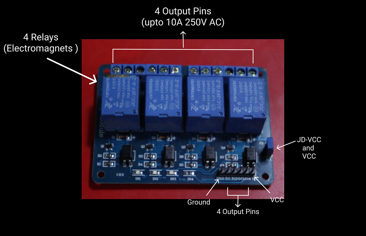
The Relay Board uses electromagnets to make and break the circuits. This one here four 4 channels, but you can easily buy up to 16 channels. The number of channels means the number of devices you can connect at once. This relay can handle up to 10A 250V AC. There are four input pins (IN 1–4) to control four relays. You can use Node-MCU to power the board, but it is a good idea to isolate the board from the micro-controller, to do that connect voltage pin from Node-MCU to VCC and separate 5V power supply to JD-VCC and GND.
This is where the breadboard power supply comes in.
Breadboard Power Supply
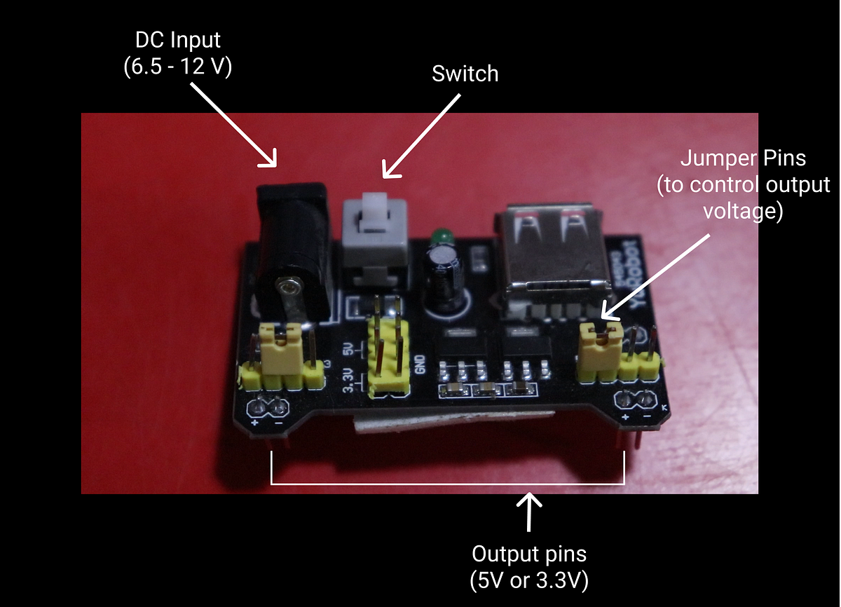
The breadboard power supply can output 5V, 3.3V, or both. There are two output pins and two jumper pins to set the configuration. It requires 6.5V–12V to function. If you are using both the pins, use the 12V input to deal with voltage drops. You can also power it using USB. There is a switch to turn on and off the device.
ESP8266 Node MCU (Microcontroller)
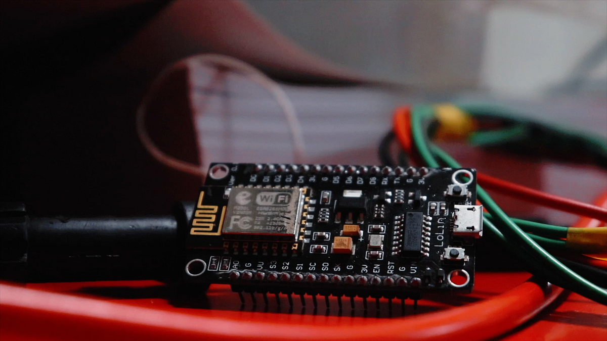
There is a lot to say about Node MCU, but I will stick to the details related to this project.
There are 16 GPIO pins in Node MCU, which can receive and send signals. Node MCU can communicate with other APIs and devices using WiFi. Node MCU required 3.3 V to power up and it can be done so using Micro-USB or Vin and GND pins. You can use pins from D1 to D8 to send signals to the relay board. We can use Arduino IDE to program Node MCU and use Blynk to send commands using our phone. We can then connect Blynk to IFTTT to connect it to Google Assistant.
Now, let’s connect!
Connecting the Pieces
Step 1 — Programming Node MCU
First, we need to program the Node MCU. The Node MCU connects to Blynk, an IoT platform, which can send commands from smartphone to Node MCU.
Make sure you have Arduino IDE installed. Now we need to add our Node MCU board to the Arduino board manager. To do this, go to Arduino > Preferences and paste the following:
https://arduino.esp8266.com/stable/package_esp8266com_index.json
in “Additional Boards Manager URL’s”, and press ok. Now go to boards manager, search “esp8266”, and install.
Next, click on Tools > boards > ESP8266 boards > Node MCU 1.0 (ESP-12E Module). Paste the above code in Arduino IDE, put your authentication code here.
char auth[] = “PUT YOUR AUTHENTICATION CODE HERE”;
To find the authentication code, use the following instructions:
Open Blynk app and create your account. Create a new project and select Node MCU as the device, choose the connection type as WiFi then click on create. This will send the auth token to your mail. For more details follow this-Getting Started.
Finally, put your WiFi SSID here:
char ssid[] = “YOUR WIFI”;
and your WiFi password here:
char pass[] = “WIFI PASSWORD”;
That’s all you need to do to control Node MCU.
Step 2 — Wiring Everything
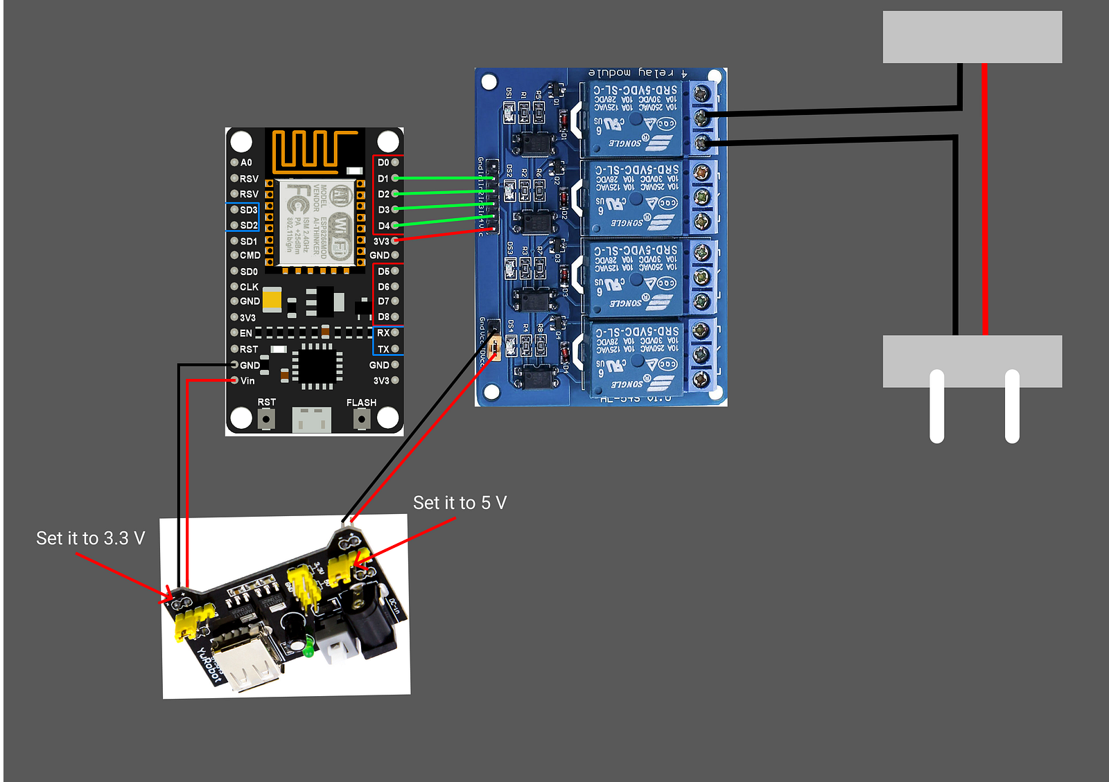
The above schematic shows the wiring of each component. D1-D4 pins in Node MCU are plugged in the relay board from In1to In4. 3.3V pin of Node MCU goes to VCC in the relay board. Take two wires and put both in 5V configuration of breadboard power supply, connect negative to GND, and positive to JD-VCC of the relay board, respectively. To power Node MCU you can either use micro-USB or use the second output of breadboard in 3.3 V configuration. Connect the positive wire to Vin and negative to GND in NodeMCU, respectively. To power breadboard power supply use a 12V DC adapter. Connect the wires of the appliance to the relay as shown above.
Step 3 — Connecting to Blynk
This will be the last step if you just want to control your devices using your phone and don’t care about voice recognition.
In the Blynk app drag 4 buttons on the main window and change the pin mode in each of the buttons to a digital pin from one to four, For D1 to D4 on Node MCU. If you are using other GPIO pins then choose those pins.
That's it! Now you can control devices using your phone.
Step 4 — Voice Activation
To use voice recognition, we need to use IFTTT. IFTTT bridges the gap between Blynk and Google Assistant. You can even use Alexa.
Create your IFTTT account and click on My Applets > create applets. There will be a big button saying “If This Then That”
Select the “This” button and then select Google assistant and click on connect. Now to create a voice command, click on “say a simple phrase”, fill in the text box according to your needs.
Now click on “That” and choose webhooks and click on connect. This will allow us to communicate with Blynk. On the URL option type the below URL, keep in mind to put your Blynk auth key there:
http://188.166.206.43/yourauthkey/update/D1
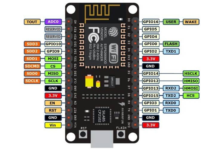
Change the D1 to your pin of Node MCU to the corresponding pin above. Ex if you are using D1 of Node MCU, type D5 in the URL, if you are using D2 of Node MCU type D4. Use the image above to find the correct value. This is because Blynk thinks that it is connecting to the Arduino UNO board and the above image is the conversion of Node MCU to Arduino UNO pins.
Change the ‘Method’ option to PUT, ‘Content Type’ as application/json, and in the ‘Body’ type
[“0”] //This means turn on
Similarly, create another applet to turn off the device and instead of putting
[“0”] type [“1”]
Now you can do the same for the other 3 appliances.
That's it! Now you have more control over your house, you can control anything you want from anywhere in the world for less than $10.
The Most Comprehensive IoT Newsletter for Enterprises
Showcasing the highest-quality content, resources, news, and insights from the world of the Internet of Things. Subscribe to remain informed and up-to-date.
New Podcast Episode

IoT Is Finally Delivering
Related Articles