CAN Bus: How It Works, Advantages, and Disadvantages
CAN Bus: How It Works, Advantages, and Disadvantages
- Last Updated: December 2, 2024
EMQ Technologies
- Last Updated: December 2, 2024

Control Area Network (CAN) bus is a serial communication protocol that allows devices to exchange data reliably and efficiently. It is widely used in vehicles, working like a nervous system to connect ECUs in the vehicle.
CAN bus was originally designed for automotive applications by Bosch in the 1980s. It is a multi-master, multi-slave, half-duplex, and fault-tolerant protocol that fits well with the requirements of automotive applications. It is simple, low-cost, and reliable and can be used in harsh environments. The CAN bus provides one point of entry for all the ECUs in the vehicle, which makes it easy to connect and diagnose.
CAN bus data can provide valuable insights into the performance and status of the connected devices. However, collecting and processing CAN bus data can be challenging due to the high data rate, low bandwidth, and variable network conditions. One possible solution to overcome these challenges is to use MQTT, enabling timely data transmission from cars to the cloud even with weak network conditions.
"The CAN bus provides one point of entry for all the ECUs in the vehicle, which makes it easy to connect and diagnose."
A Brief History of CAN Bus
The primary purpose of the CAN bus was to establish an effective communication system for automotive applications, specifically to decrease the complexity of wiring harnesses in vehicles.
In 1986, Bosch introduced their initial CAN protocol, which quickly gained momentum among automakers due to its reliability and robustness. By 1993, it became an international standard under ISO-11898. To summarize the evolution of the protocol:
- 1991: Mercedes-Benz becomes one of the first automobile manufacturers to implement CAN bus in their W140 S-Class model.
- 2004: The introduction of CAN FD (Flexible Data Rate), providing higher data rates and larger payloads than traditional CAN networks.
- 2015: Adoption of ISO-16845:2015 as a conformance test plan for devices implementing both classic CAN and CAN FD protocols.
Apart from automotive applications, other industries have embraced this versatile network protocol over time. Today, it is used in industrial automation systems (CANopen) and marine electronics (NMEA 2000). Its widespread adoption is mainly attributed to its ability to operate reliably even under harsh conditions while maintaining low-cost implementation requirements.
How Does a CAN Bus Work?
The CAN bus is a decentralized communication protocol. Its decentralized approach makes it ideal for applications in automotive and industrial systems where reliability and real-time performance are essential.
In a CAN network, all nodes are connected via twisted-pair wiring or optical fiber cables. Each node has its microcontroller responsible for processing incoming messages and sending outgoing ones. Data is broadcasted by a node on the shared bus, allowing all other nodes to receive it. The primary stages of the communication process are:
- Arbitration: To prevent collisions when multiple nodes attempt to transmit simultaneously, CAN uses an arbitration process based on message priority. The lower the identifier value of a message, the higher its priority.
- Error detection: Built-in error detection mechanisms ensure data integrity within CAN networks. These include cyclic redundancy checks (CRC), frame check sequences (FCS), and acknowledgment bits from receiving nodes.
- Fault confinement: If any node detects an error or malfunctions during transmission, it will enter an "error passive" state until proper operation resumes. This prevents faulty transmissions from affecting overall system functionality.
This combination of features allows CAN buses to maintain high levels of efficiency while ensuring reliable communication between different components in complex systems like vehicles or factory automation equipment.
Message Structure in the CAN Protocol
The message structure in a CAN bus system is crucial for efficient communication between devices. The protocol uses a data frame format that consists of several fields, including an identifier, control field, data field, and error detection mechanism.
- Identifier: This unique value determines the priority of each message on the network. In standard 11-bit identifiers (CAN 2.0A), there are up to 2048 different priorities available. Extended 29-bit identifiers (CAN 2.0B) provide even more options with over half a billion distinct values.
- Data Length Code (DLC): Located within the control field, this code specifies how many bytes are present in the data field - ranging from zero to eight bytes.
- Data Field: Contains actual information being transmitted across nodes in byte-sized segments.
- Cyclic Redundancy Check (CRC): A built-in error detection mechanism that ensures reliable communication by detecting transmission errors and requesting retransmission if necessary.
- Acknowledgment Slot: A single bit used by receiving nodes to acknowledge the successful receipt of messages or indicate errors requiring retransmission.
- Error Frame: An optional part of CAN messaging that allows nodes to signal when they detect an issue with their own transmissions or received messages from other devices on the network.
Types of CAN
Here are the three main types of CAN:
#1: Low-Speed CAN
Low-Speed CAN, also known as fault-tolerant or ISO 11898-3, operates at speeds up to 125 kbps. It is designed for less critical systems like body control modules, door locks, window controls, etc., where data transmission speed isn't vital. Its key feature is the ability to continue functioning even when one wire in the bus fails.
#2: High-Speed CAN
High-Speed CAN, or ISO 11898-2, can reach speeds up to 1 Mbps. This type of network is suitable for more time-sensitive applications such as engine management systems and electronic braking systems due to its faster data transfer rates compared to low-speed counterparts. However, it lacks fault tolerance capabilities found in low-speed networks.
#3: CAN FD (Flexible Data Rate)
CAN FD, introduced by Bosch in 2012, is an extension of high-speed networks with increased data rates—up to 5 Mbps—while maintaining backward compatibility with existing high-speed devices. The primary advantage of this technology lies in its ability to transmit larger payloads more efficiently than traditional CAN, making it ideal for modern vehicles with increasingly complex electronic systems.
CAN Bus: Advantages and Challenges
Advantages
The CAN bus data can provide valuable insights into the performance, health, and behavior of a vehicle. Collecting CAN bus data to the cloud is a powerful way to leverage the potential of vehicle data through big data analysis.
By applying machine learning, artificial intelligence, or other analytical tools to the collected data from a large number of vehicles, vehicle manufacturers can gain valuable insights and leverage them to optimize vehicle performance.
- Detecting, troubleshooting, and predicting faults: By analyzing the CAN bus data, one can identify any abnormal or erroneous signals from the devices and sensors. This can help diagnose the root cause of a problem and fix it before it leads to more damage or safety issues. Manufacturers can also train machine learning models to predict faults by feeding the collected data to the model.
- Visualizing vehicle data: With the collected data, users can develop a system to display the aggregated data on a dashboard that allows users to filter, sort, and compare different vehicles and metrics. The dashboard also provides alerts and recommendations based on the data analysis. The system enables users to gain insights into their performance.
- Vehicle road coordination: The collected data can be calculated together with the road infrastructure data to build a vehicle road coordination system.
In the AI era, data is the most valuable property. By collecting data from cars to the cloud and then distributing it to all kinds of data infrastructure like databases, and data lakes, users can leverage the data for nearly all kinds of applications.
Challenges
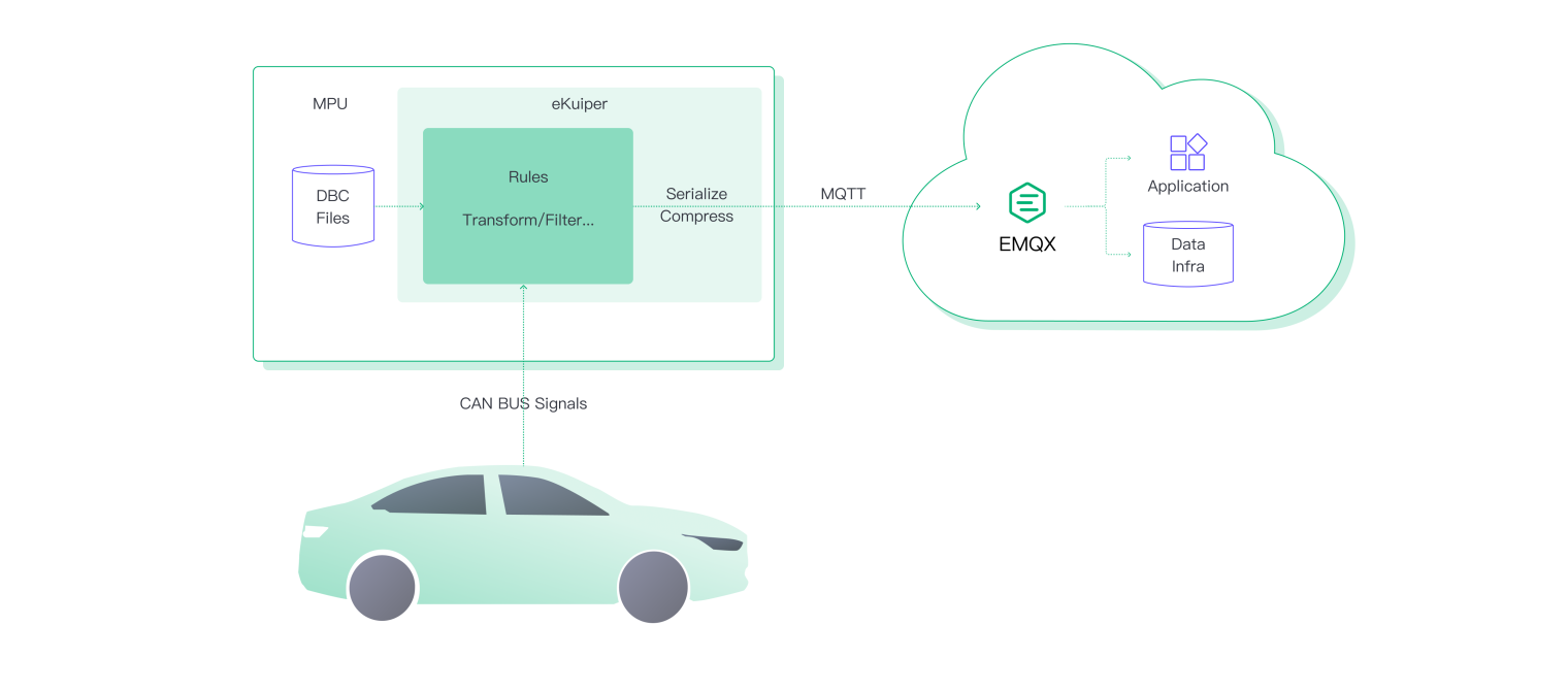
Collecting CAN bus data locally on the vehicle is pretty mature. However, it can be challenging to collect and process the CAN bus data and transfer the insight to the cloud in real time due to the high data rate, low bandwidth, and variable network conditions. Thus, transferring all the CAN bus data to the cloud for processing is impractical. Instead, one can collect and process the CAN bus data locally on the edge side to reduce the data volume and transfer the insight to the cloud in real time.
You'll need at least two components to build such a solution:
- Edge computing engine: An edge computing engine can collect only the needed CAN bus signals, flexibly process them and trigger MQTT transfer actions in real time.
- MQTT broker in the cloud: An MQTT broker can help transfer the processed CAN bus data to the cloud in real time.
The Most Comprehensive IoT Newsletter for Enterprises
Showcasing the highest-quality content, resources, news, and insights from the world of the Internet of Things. Subscribe to remain informed and up-to-date.
New Podcast Episode

IoT Is Finally Delivering
Related Articles

Related Solutions
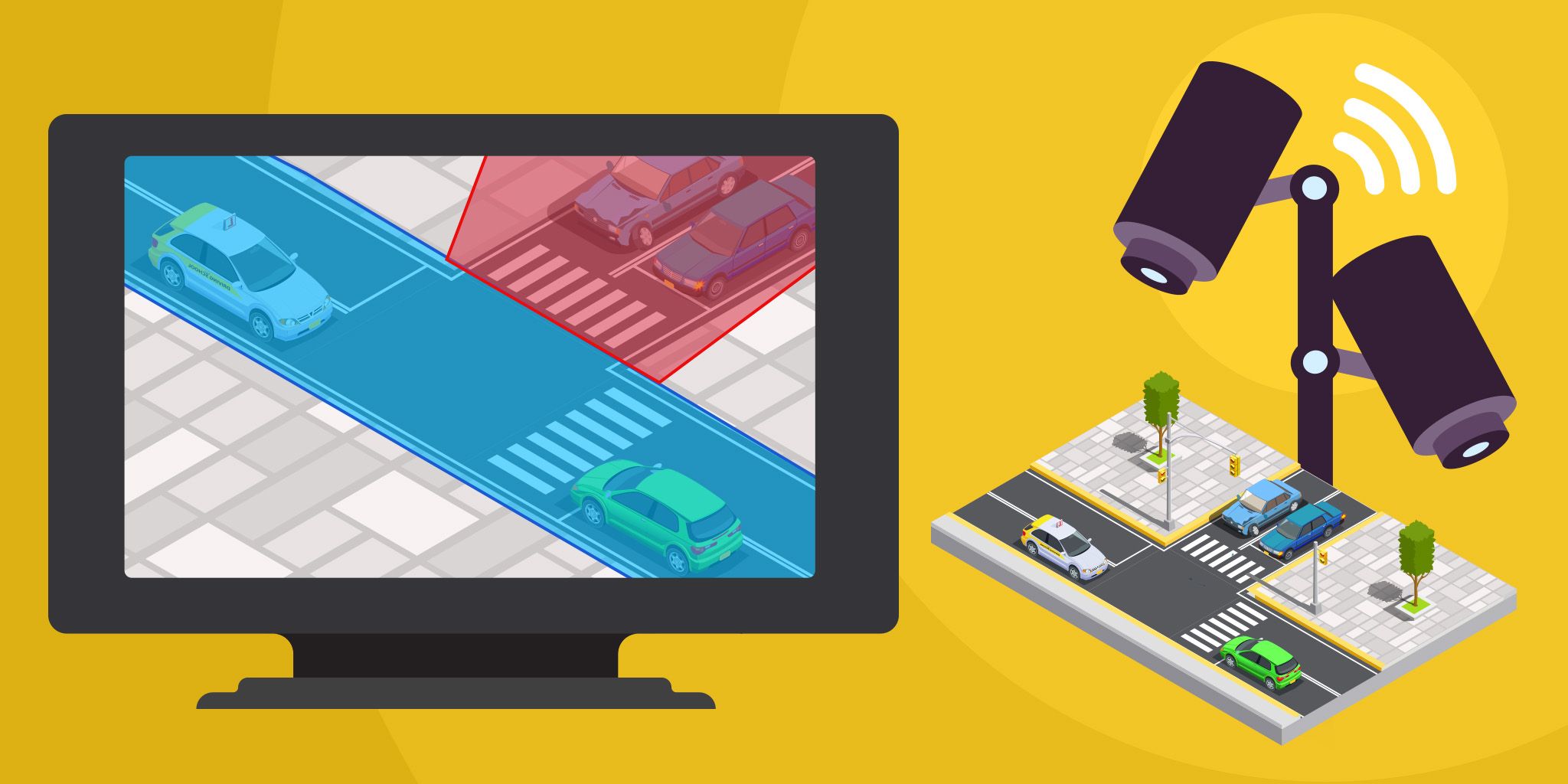
Traffic Optimization for Cities
Turn existing city cameras into AI‑powered intersection monitors that deliver real‑time vehicle counts, speed tracking, and violation detection.
Turn existing city cameras into AI‑powered intersection monitors that deliver real‑time vehicle counts, speed tracking, and violation detection.
Iveda
Iveda

Emergency Department Workflow Management
Gain a complete view of patient flow, staff activity, and resource availability to reduce wait times, improve satisfaction, and optimize throughput.
Gain a complete view of patient flow, staff activity, and resource availability to reduce wait times, improve satisfaction, and optimize throughput.
Vizzia Technologies
Vizzia Technologies
Sewer Level Monitoring
Real‑time sewer level data and early alerts to prevent overflows, prioritize maintenance, and proactively manage networks.
Real‑time sewer level data and early alerts to prevent overflows, prioritize maintenance, and proactively manage networks.
Kallipr
Kallipr
Related Solutions
Smart Cities
Traffic Optimization for Cities
Turn existing city cameras into AI‑powered intersection monitors that deliver real‑time vehicle counts, speed tracking, and violation detection.
Iveda
Healthcare
Emergency Department Workflow Management
Gain a complete view of patient flow, staff activity, and resource availability to reduce wait times, improve satisfaction, and optimize throughput.
Vizzia Technologies
Utilities
Sewer Level Monitoring
Real‑time sewer level data and early alerts to prevent overflows, prioritize maintenance, and proactively manage networks.
Kallipr