How To Build a CNC Controller in Python
How To Build a CNC Controller in Python
- Last Updated: December 2, 2024
DataArt
- Last Updated: December 2, 2024

CNC machine controllers are typically implemented using the C or C++ programming language and running on OS-less or real time operating systems with simple microcontrollers.
I will describe how to build a CNC controller, a 3D printer in particular, using modern ARM boards — Raspberry Pi with a modern high level language — Python. Such a modern approach opens a wide range of integration options with other cutting edge technologies, solutions, and infrastructures, which makes the whole project developer-friendly.
About the Project
Modern ARM boards typically use Linux as a reference operating system. This gives us the entire Linux infrastructure with all the Linux software packages. We can host a web server on a board, use a Bluetooth connectivity, use OpenCV for image recognition, build a cluster of boards, etc. These are well-known tasks that can be implemented on ARM boards, and they can be really useful for custom CNC machines. For example, auto positioning using compuvision can be very handy for some machines.
Linux is not a real time operating system. So, we can’t generate pulses with the required timings to control stepper motors directly from the board pins with running software, even as a kernel module. Then, how can we use steppers and high-level Linux features?
We can use two chips — one microcontroller with a classic CNC implementation; and an ARM board connected to this microcontroller via UART. What if there are no suitable firmware features for this microcontroller? What if we need to control additional axes that are not implemented in the microcontroller?
Any modifications to the existing C/C++ firmware will require plenty of development time and efforts. Let’s see if we can make it easier and even save money on microcontrollers by simply removing them.
PyCNC
PyCNC is a free open-source high-performance G-code interpreter and CNC/3D-printer controller. It can run on various Linux-powered ARM-based boards, such as Raspberry Pi, Odroid, Beaglebone and others. This gives you the flexibility to pick any board and use everything that Linux offers. And you can keep the entire G-code runtime on one board without the need for a separate microcontroller for real-time operation.
Choosing Python as the main programming language significantly reduces the code base compared to C/C++ projects, reduces the boilerplate and microcontroller-specific code, and makes the project accessible to a wider audience.
How It Works
The project uses DMA (Direct Memory Access) on the chip hardware module. It simply copies the GPIO states buffer allocated in RAM to the actual GPIO registers. And this copying process is synchronized by the system clock and works completely independently from the CPU cores. Thus, a sequence of pulses for the stepper motors axis is generated in memory and then the DMA precisely sends them out.
Let’s dig deeper into the code to understand the basics and how to access hardware modules from Python.
GPIO
A General Purpose Input Output module controls pin states. Each pin can have low or high state. When we program the micro-controller, we usually use SDK defined variables to write to that pins. For example, to enable a high state for pins 1 and 3:
PORTA = (1 << PIN1) | (1 << PIN3)
If you look in the SDK, you will find the declaration of this variable, and it will look similar to:
#define PORTA (*(volatile uint8_t *)(0x12345678))It’s just a pointer. Not for the location in RAM, but for the address of physical processor, and the actual GPIO module is located at this address. To manage pins we can write and read data. Raspberry Pi’s ARM processor is not an exception and it has the same module. To control pins, we can write/read data. We can find the addresses and data structures in the official documentation for processor peripherals.
When we run a process in the user’s runtime, the process starts in the virtual address space, and the actual peripheral is accessible directly. But we can still access real physical addresses with ‘/dev/mem’ device.
Here is some simple code in Python that controls a pin’s state using this approach:
Let’s break it down line by line:
- Lines 1–6: headers, imports.
- Line 7: open
‘/dev/mem’device access to the physical address. - Line 8: we use the memmap system call to map a file (though in our case this file represents physical memory) into the process’s virtual memory. We specify the length and offset of the map area. For the length we take the page size. And the offset is
0x3F200000. The documentation says that the bus address0x7E200000contain GPIO registers and we need to specify the physical address. The documentation says (page 6, paragraph 1.2.3) that the0x7E000000bus address is mapped to the0x20000000physical address, but this documentation is for Raspberry 1.
Please note, that all module bus addresses are the same for Raspberry Pi 1–3, but this map was changed to0x3F000000for RPi 2 and 3. So, the address here is0x3F200000. For Raspberry Pi 1 change it to0x20200000.
After this, we can write to our process’s virtual memory, but it actually writes to the GPIO module. - Line 9: close the file handle, since we don’t need to store it.
- Lines 11–14: we read and write to our map with the
0x08offset. According to the documentation it is the GPFSEL2 GPIO Function Select 2 register. And this register controls pin functions. We set (clear all, then set with the OR operator) 3 bits with the 3rd bit set to 001 and this value means that the pin works as an output. There are many pins and possible modes for them, that’s why the register for modes is divided into several registers where each contain the modes for 10 pins. - Lines 16 and 22: set up the ‘Ctrl+C’ interruption handler.
- Line 17: infinite loop.
- Line 18: set the pin to the high state by writing to the GPSET0 register. Please note, Raspberry Pi doesn’t have registers like PORTA (AVR microcontrollers have), we can’t write the whole gpio state of all pins. There are just SET and CLEAR registers which are used to set and clear specified with bitwise mask pins.
- Lines 19 and 21: delay
- Line 20: set pin to low state with the GPCLR0 register.
- Lines 25 and 26: switch pin to default, input state. Close the memory map.
This code should be ran with superuser privileges, name the file ‘gpio.py’ and run it with ‘sudo python gpio.py’. If you have a LED connected to pin 21, it will blink.
DMA
Direct Memory Access is a special module that is designed to copy memory blocks from one area to another. We will copy data from the memory buffer to the GPIO module. First of all, we need a solid area in physical RAM that will be copied.
There are a few possible solutions:
- For example, we can create a simple kernel driver that will allocate, lock, and report the address of this memory.
- In some implementations virtual memory is allocated and uses
‘/proc/self/pagemap’to convert the address to the physical one. I wouldn't recommend to use this approach, especially when we need to allocate a big area. Any virtually allocated memory (even locked, see the kernel documentation) can be moved to the physical area. - All Raspberry Pi have a
‘/dev/vcio’device, which is a part of the graphic driver and can allocate physical memory for us. An official example shows how to do it. And we can use it instead of creating our own.
The DMA module itself is just a set of registers that are located somewhere at a physical address. We can control this module via these registers. Basically, there are source, destination, and control registers. Let’s check some simple code that shows how to use the DMA module to manage the GPIO. Since additional code is required to allocate physical memory with ‘/dev/vcio’, we will use a file with an existing CMAPhysticalMemory class implementation. We will also use the PhysicalMemory class, which performs the trick with memap from the previous sample.
Let’s break it down line by line:
- Lines 1–3: headers, imports.
- Lines 5–6: constants with the channel DMA number and GPIO pin that we will use.
- Lines 8–15: initialize the specified GPIO pin as an output and light it up for a half second for visual control. In fact, it’s the same thing we did in the previous example, written in a more pythonic way.
- Line 17: allocates 64 bytes in physical memory.
- Line 18: creates special structures — control blocks for the DMA module. The following lines break the structure of this block. Each field has a length of 32 bit.
- Line 19: transfers information flags. You can find full description of each flag on page 50 of the official documentation.
- Line 20: source address. This address must be a bus address, so we call
get_bus_address(). The DMA control block must be aligned by 32 bytes, but the size of this block is 24 bytes. So we have 8 bytes, which we use as storage. - Line 21: destination address, in our case, is the address of SET register of the GPIO module.
- Line 22: transmission length — 4 bytes.
- Line 23: stride. We do not use this feature, set 0.
- Line 24: address of the next control block, in our case, next 32 bytes.
- Line 25: padding, but since we used this address as a data source, put a bit, which should trigger GPIO.
- Line 26: padding.
- Lines 28–37: fill in the second DMA control block. The difference is that we write to CLEAR GPIO register and set our first block as a next control block to loop the transmission.
- Lines 38–39: write control blocks to physical memory.
- Line 41: get the DMA module object with the selected channel.
- Lines 42–43: reset the DMA module.
- Line 44: specify the address of the first block.
- Line 45: run the DMA module.
- Lines 49–52: clean up. Stop the DMA module and switch the GPIO pin to the default state.
Let’s connect the oscilloscope to the specified pin and run this application (do not forget about sudo privileges). We will observe ~1.5 MHz square pulses:
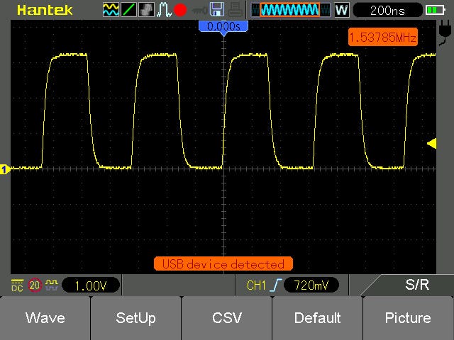
Image Credit: DataArt
DMA challenges
There are several things that you should take into consideration before building a real CNC machine. First, the size of the DMA buffer, obviously, can be hundreds of megabytes. The second one is related to the fact that the DMA module is designed for a fast data copying.
If several DMA channels are working, we can go beyond the memory bandwidth, and buffer will be copied with delays that can cause jitters in the output pulses. So, it’s better to have some synchronization mechanism.
To overcome this, I created a special design for control blocks:
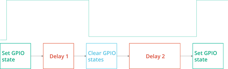
The oscillogram at the top of the image shows the desired GPIO states. The blocks below represent the DMA control blocks that generate this waveform. “Delay 1” specifies the pulse length and “Delay 2” is the pause length between pulses. With this approach, the buffer size depends only on the number of pulses.
For example, for a machine with 200mm travel length and 400 pulses per mm, each pulse would take 128 bytes (4 control blocks per 32 bytes), and the total size will be ~9.8MB. Of course, we would have more than one axis, though most of the pulses would occur at the same time, and it would be dozens of megabytes, not hundreds.
The second challenge, related to synchronization, was solved by introducing temporary delays through the control blocks. The DMA module has a special feature: it can wait for a special ready signal from the module where it writes data. The most suitable module for us is the PWM module, which will also help us with synchronization.
The PWM module can serialize the data and send it with fixed speed. In this mode, it generates a ready signal for the FIFO buffer of the PWM module. So, let’s write data to the PWM module and use it only for synchronization.
Basically we need to enable a special flag in the PERMAP of the transfer information flag and run the PWM module with the desired frequency. The implementation is quite long, you can study it yourself. Instead, let’s create some simple code that can use the existing module to generate precise pulses.
import rpgpio
PIN=21
PINMASK = 1 << PIN
PULSE_LENGTH_US = 1000
PULSE_DELAY_US = 1000
DELAY_US = 2000

g = rpgpio.GPIO()
g.init(PIN, rpgpio.GPIO.MODE_OUTPUT)

dma = rpgpio.DMAGPIO()
for i in range(1, 6):
 for i in range(0, i):
 dma.add_pulse(PINMASK, PULSE_LENGTH_US)
 dma.add_delay(PULSE_DELAY_US)
 dma.add_delay(DELAY_US)
dma.run(True)

raw_input(“Press Enter to stop”)
dma.stop()
g.init(PIN, rpgpio.GPIO.MODE_INPUT_NOPULL)
The code is pretty simple and there is no sense to break it down. If you run this code and connect an oscilloscope, you will see:
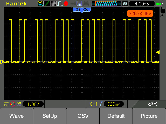
Image Credit: DataArt
And now we can create real G-code interpreter and control stepper motors. But wait, it is already implemented. You can use this project, as it’s distributed under the MIT license.
Hardware
The Python project can obviously be adopted for your purposes, but in order to inspire you, I will describe the original hardware implementation of this project — a 3D printer. It basically contains the following components:
- Raspberry Pi 3
- 4 A4988 or DRV8825 module
- RepRap Prusa i3 frame with equipment (end-stops, motors, heaters, and sensors)
- 12V 15A power supply unit
- LM2596S DC-DC step down converter module
- MAX4420 chip
- ADS1115 analog to digital converter module
- UDMA133 IDE ribbon cable
- Acrylic glass
- PCB stands
- Set of connectors with 2.54mm step
The 40-pin IDE ribbon cable is suitable for the Raspberry Pi 40 pins connector, but the opposite end requires some work. Cut off the existing connector from the opposite end and crimp connectors to the cable wires.
The RAMPSv1.4 board was originally designed for connection to the Arduino Mega connector, so there is no easy way to connect this board to the Raspberry Pi. The following method allows to simplify the boards connection. You will need to connect less than 40 wires.

Image Credit: DataArt
I hope this connection diagram is fairly simple and is easily duplicated. It’s better to connect some pins (2nd extruder, servos) for future use, even if they are not currently needed.
You might be wondering, why do we need the MAX4420 chip? The Raspberry Pi pins provide 3.3V for the GPIO outputs, and the pins can provide a very small current, which is not enough to switch the MOSFET gate. In addition, one of the MOSFETs works under the 10A load of a bed heater.
As a result, with a direct connection to a Raspberry Pi, this transistor will overheat. Therefore, it is better to connect a special MOSFET driver between the highly loaded MOSFET and Raspberry Pi. It can switch the MOSFET in a an efficient way and reduce its heating.
The ADS1115 is an analog-to-digital converter (ADC). Since Raspberry Pi doesn’t have an embedded ADC module, I used an external one to measure the temperature from the 100k Ohm thermistors. The RAMPSv1.4 module already has a voltage divider for the thermistors. The LM2596S step down converter must be adjusted to a 5V output, and it is used to power the Raspberry Pi board itself.
Now it can be mounted on the 3D printer frame and the RAMPSv1.4 board should be connected to the equipped frame.
That’s it. The 3D printer is assembled, and you can copy the source code to the Raspberry Pi and run it. sudo ./pycnc will run it in an interactive G-Code shell. sudo ./pycnc filename.gcode will run a G Code file. Check the ready config for Slic3r.
And in this video, you can see how it actually works.
Written by Nikolay Khabarov, Solutions Architect at DataArt.
The Most Comprehensive IoT Newsletter for Enterprises
Showcasing the highest-quality content, resources, news, and insights from the world of the Internet of Things. Subscribe to remain informed and up-to-date.
New Podcast Episode

IoT Is Finally Delivering
Related Articles


Related Solutions

RTK Positioning for Robotics and Field Machines
High-precision positioning. Achieve centimeter-level accuracy without the complexity of building custom hardware from scratch.
High-precision positioning. Achieve centimeter-level accuracy without the complexity of building custom hardware from scratch.
Kalmix
Kalmix
Staff Management and Location Tracking for Coworking Spaces
Gain real-time visibility of third-party staff like security or janitors with BLE beacons and smart LTE badges.
Gain real-time visibility of third-party staff like security or janitors with BLE beacons and smart LTE badges.
Minew
Minew
Related Solutions
Industrial
RTK Positioning for Robotics and Field Machines
High-precision positioning. Achieve centimeter-level accuracy without the complexity of building custom hardware from scratch.
Kalmix
Buildings & Facilities
Staff Management and Location Tracking for Coworking Spaces
Gain real-time visibility of third-party staff like security or janitors with BLE beacons and smart LTE badges.
Minew