Fueling Up for Autonomous Driving with Optimized Battery Designs
Fueling Up for Autonomous Driving with Optimized Battery Designs
- Last Updated: December 2, 2024
E-Peas Semiconductors
- Last Updated: December 2, 2024


Imagine a future where everyone on the road is using an Autonomous Vehicle (AV). It seems straight out of the futuristic Netflix® television series Black Mirror, right? Now, imagine if these autonomous vehicles emit dirty exhaust and need regular visits to the gas stations to fill up. It seems anachronistic, like fully outfitting a smart home with the latest IoT gadgets…only to connect it all with dial-up internet.
Autonomous vehicles aren’t, and won’t be, powered by solely gasoline. Instead, the central question is whether only completely electric AVs should be made or if AVs with hybrid engines can be produced as well. There are arguments to be made for each side.
Electric vehicle batteries need to be optimized for autonomous driving applications, with factors like battery power output taken into account.
To Hybrid or Not To Hybrid
On one side of the coin, many of the automotive companies developing self-driving cars expect their primary use — at least at first — to center on ride-sharing, like taxis without drivers. A hybrid engine that combines gas and electric power enables cars to spend more time on the road (and making money) than charging in a garage.
On the other side, some car companies, along with environmental organizations, are concerned that since these vehicles would likely be driving passengers and making deliveries nonstop, the level of pollution would multiply exponentially, wreaking havoc on the environment.
Either way, electric vehicle batteries need to be optimized for autonomous driving applications, with factors like battery power output and degradation taken into account. Using the COMSOL Multiphysics® software and add-on Batteries & Fuel Cells Module, scientists and engineers can study and design battery systems for both hybrid and all-electric autonomous vehicles.
Battery Designs with Optimal Power Output
By nature, autonomous vehicles involve more electronic components than regular cars. Going beyond the car itself (as well as its lights, alarms, and radio), AVs contain navigation systems and detection and ranging equipment. Large amounts of power consumption means that batteries will get drained faster than normal. Batteries for AVs need to be designed to last longer and output more power so they can keep up with energy demands.
Battery Management Systems
In both hybrid and all-electric vehicles, the battery management system (BMS) is an extremely important design factor. By accurately monitoring the battery activity, the BMS maximizes the energy output, lifetime, and safety. Modeling a lithium-ion battery under isothermal conditions can help you analyze factors that are important in a BMS design, including:
- Voltage
- Polarization (voltage drop)
- Internal resistance
- State-of-charge (SOC)
- Rate capability
Consider a model (below) of a 1D lithium-ion battery made of graphite and lithium-ion manganese oxide (LMO), a cost-efficient and thermally stable fuel cell material, from the default settings in the material library in the Batteries & Fuel Cells Module.
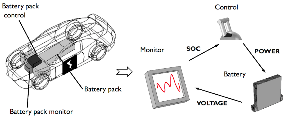
A schematic of the key components of a BMS for electric vehicles.
The battery model is made up of four domains:
- Negative porous electrode
- Separator
- Positive porous electrode
- Electrolyte
The model enables you to test inputs to see how they affect the overall performance of the battery. These factors can include the initial cell voltage; battery capacity; thickness of the separator and electrodes; and cell SOC, which is the percentage of charge remaining in an electric or hybrid car’s battery pack, analogous to the level of the fuel gauge in a gas-powered vehicle.
Drive Cycle
Vehicles operate according to a specific drive cycle, during which the varying temperature and voltage of the battery are monitored. The drive cycle tells the BMS what the SOC of the battery is: in effect, whether the battery is empty or full. Then, a control unit stops the discharge (if the battery is empty) or charge (if the battery is full).
The 1D model can be expanded to include a thermal analysis in order to perform drive-cycle monitoring. Consider a battery cell that is subjected to a drive cycle for a hybrid vehicle.
Engineers can simulate the drive cycle of the lithium-ion battery to predict its performance, analyze parameters that are hard to measure or validate experimental results. A few of the factors that affect a battery’s drive cycle include:
- Internal resistance and polarization in each part of the battery cell
- Cell SOC
- SOC of each electrode material
- Local temperature
- Materials
The current load input can be imported into the model from external drive cycle data, such as time versus C-rate (a battery’s discharge rate relative to its maximum capacity). In this case, the imported data corresponds to values that are typical of a hybrid electric vehicle. The analysis can tell you a lot about a battery’s drive cycle, including the cell voltage, electric potential, and total polarization. It is also possible to determine the SOC of the cell and electrodes at load (as well as the temperature) during the drive cycle.
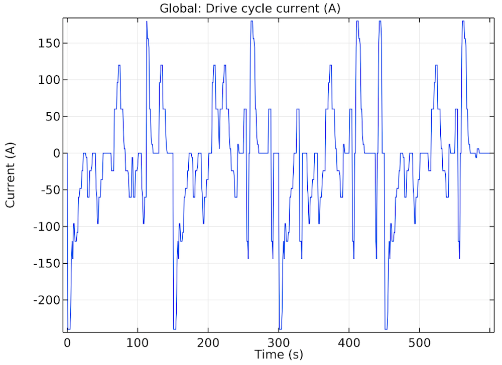
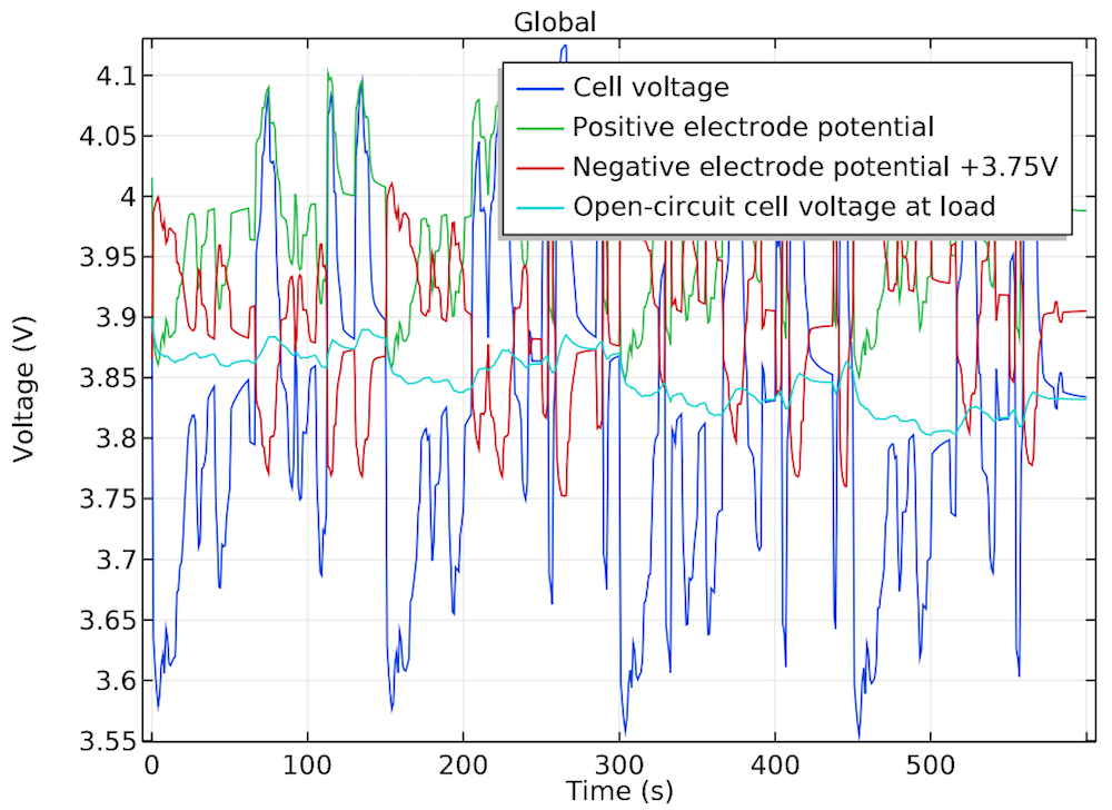
The drive cycle (left) and simulation results showing the cell voltage over the course of the drive cycle (right).
The results of this example show that the drive cycle is suited for this type of battery design. They also show that the heat management could be improved in order for the battery to handle longer drive cycles. As we’ll discuss in the next section, optimizing the drive cycle of AVs will affect their level of success in the consumer transportation market.
Power vs. Energy Evaluation
Rate capability is used to determine whether a battery is designed for its intended purpose. There are two options: energy optimized and power optimized. Energy-optimized batteries have a large capacity or energy supply but relatively low current loads, which makes them a good choice for use in portable electronic devices. For hybrid and electric vehicles, power-optimized batteries are the better option. These batteries have a relatively low capacity but high current loads; for example, they can be recharged at very high currents.
Going back to the 1D lithium-ion battery model, you can perform a power versus energy evaluation to determine the battery’s rate capability. The simulation investigates, under different current loads, the discharge of the battery from its fully charged state and the charge of the battery from its fully discharged state.
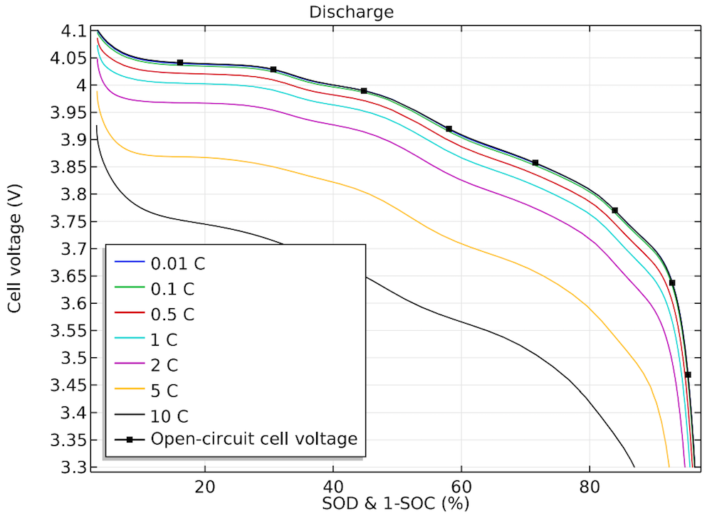
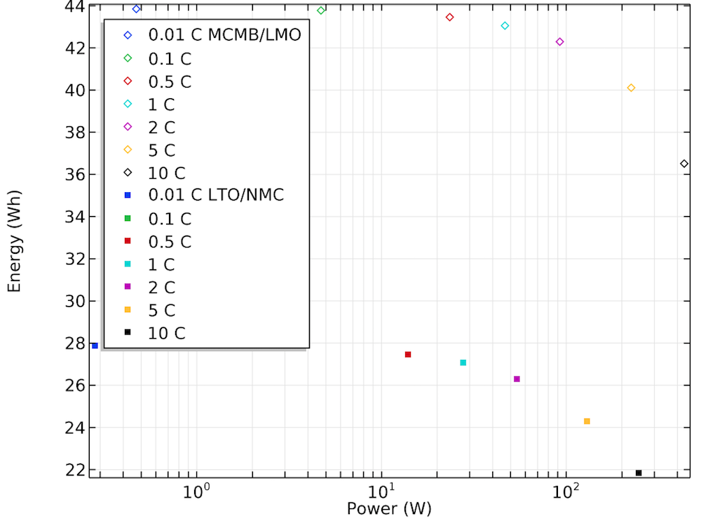
The results show the cell voltage during the different current loads and can be used to compare the energy and power outputs of the battery design. The Ragone plot (above, right) demonstrates the effect of battery chemistry and discharge rate on the capacity of the battery.
Modeling Battery Degradation
The transition to autonomous driving is not going to happen overnight. Many innovators think that when AVs first hit the market, it will be in the form of ride-sharing, not individual cars for a single person or family. Logically, this means that each AV in a ride-sharing company’s fleet will be accessed by about ten riders per day instead of one and operate around the clock instead of during one person’s schedule.
In effect, the use of AVs primarily for ride-sharing will cause car batteries to wear down much faster than those in regular, single-household vehicles. This is where capacity fade analysis comes into play.
Capacity Fade
Batteries undergo both capacity fade and power fade, but there’s a difference. Power fade is the reduced battery voltage for the given discharge rate. Capacity fade is the loss of battery capacity, regardless of the current rate.
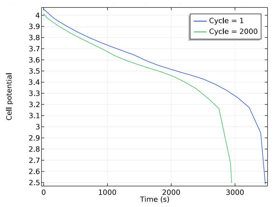
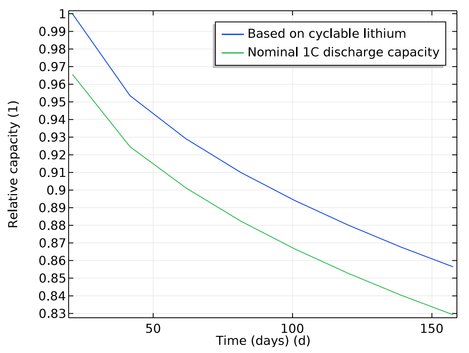
Cell voltage during the discharge cycle (left) and battery capacity over the total cycle (right).
The different cell materials that make up a battery, as well as the various combinations between them, cause different rates of aging and can even accelerate the process, and therefore the loss of battery capacity. Certain factors that affect battery cell aging and degradation include:
- Stage of the load cycle
- Potential
- Local concentration
- Temperature
- Direction of the current
By performing a time-dependent analysis of a battery during the cycle, it is possible to find the voltage during discharge and compare the capacity to both the total accumulated cycling time and the total number of cycles. It is also possible to analyze the electrolyte volume fraction and solid electrolyte interphase (SEI) film potential drop versus the cycle number and the local SOC on the separator-electrode boundaries. (The SEI provides the electrolytes with insulation and conductivity.) These factors can aid in the design of batteries that are optimized for long-term and constant use in AVs.
The Most Comprehensive IoT Newsletter for Enterprises
Showcasing the highest-quality content, resources, news, and insights from the world of the Internet of Things. Subscribe to remain informed and up-to-date.
New Podcast Episode

How Smart Labels Transform the Supply Chain
Related Articles


